PROTECTIVE SYSTEMS FOR USE IN POTENTIALLY EXPLOSIVE ATMOSPHERES: BASIC CONCEPTS
ATEX device manufacturers use different types of protection to attain specific Equipment Protection Levels (EPL). These protection techniques undergo continuous advancements in both technical and regulatory aspects. Nevertheless, the ones with a longstanding track record remain the most widely utilised.

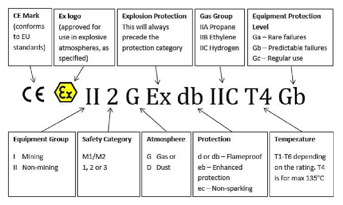
*Equipment Protection Level (EPL) is defined by the international standard IEC/EN 60079. The assigned EPL of equipment indicates the risk level or ‘likelihood’ that the equipment can become a source of ignition. The EPL depends on the explosive atmosphere type: gas (G), dust (D) or mines (M).
Introduction
The in-depth knowledge of the protection methods is the responsibility of manufacturers and regulatory bodies, both of whom must ensure compliance with requirements. Understanding some aspects of the protection modes is an essential requirement for a safe and successful installation.
Before going into detail of the most used methods of protection, it is necessary to elaborate on some of the basic concepts and the terminology. Let us start by gaining an understanding of the word ‘Explosion’.
Combustion and explosion
The ATEX directive defines the explosive atmosphere as: a mixture containing air, at atmospheric conditions, flammable substances in the state of gas, vapours, mists, or dusts in which, after ignition, the combustion spreads to the entire unburned mixture.
The explosion covered by the ATEX directive is therefore a combustion that occurs between reactants at standard atmospheric pressure.
The combustion is an exothermic chemical reaction, which liberates heat. Normally, combustion generates heat that is released into the air without generating pressure differences. For example, a log of wood that burns in a forest or inside a fireplace. In this scenario the heat has time to disperse, giving thermal energy to the air and to the surrounding matter without producing sudden changes in pressure. In the case of an explosion, on the other hand, the reaction rate is such that the volume of the substances involved increases without being able to release the heat generated by the reaction, the gases expand generating pressure on the surfaces or on the gases not yet compressed.
For example: in an enclosed space, commencing with the reactants at atmospheric pressure, standard explosion parameters may entail a peak pressure of 10 atmospheres and a reaction velocity of 102 m/s.
Furthermore, compared to a common combustion reaction, the explosion is self-sustained by the propagation of a flame front through the explosive atmosphere.
The fire triangle
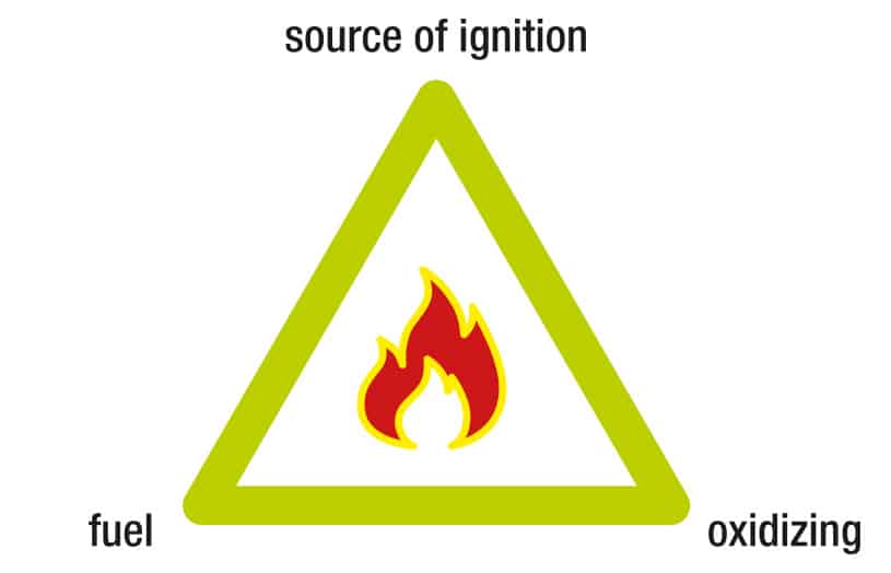
To address the issue of explosion risk, as is done for the risk of fire, we talk about the schematic concept of the fire triangle.
It is a concept often reported in fire prevention courses and in fact reflects the explosion/combustion correspondence.
The triangle summarises the three basic conditions that must be met to start a fire or explosion.
An explosion can only occur if they are present in the same place at the same time:
- Fuel
- Oxidising or oxygen
- A source of ignition

Sources of ignition in electrical equipment
Among the ignition sources, restricting the field of those most likely to be found in an electrical device, we have to include sparks / arcs of electrical origin, electrostatic charges and hot surfaces (For example the surface of a running engine). Additionally, ignition can also be attributed to electromagnetic waves, radio frequencies, and optical radiation.
The mitigation of the explosion risk: basic criteria
When designing electrical devices with EPL ratings of Ga, Gb, or Gc, it is imperative to prevent the simultaneous presence of the three elements comprising the combustion triangle
To do this we follow three basic criteria:
- Containment
- Segregation
- Prevention
Containment
The explosion can occur but is confined to a well-defined volume by means of special enclosures. Additionally, any potential for the explosion to ignite the surrounding atmosphere is prevented. The containment of the explosion is the basis of the explosion protection method Ex-d whose enclosures are often defined flameproof.
Segregation
The ignition sources are physically separated from the explosive atmosphere. Segregation forms the core principle of protection methods Ex p pressurisation, Ex m encapsulation, Ex o oil immersion, Ex q powder filling, Ex nR limited breathing.
Prevention
The ignition of the explosive atmosphere is avoided by controlling the energies involved, as in the intrinsically safe protection mode, or by increasing standard industrial safety criteria, as in the increased safety protection mode. This criterion is the basis of the increased safety Ex-e and intrinsically safe Ex-i protection mode.
| BASIC CRITERIA | DESCRIPTION | METHOD OF PROTECTION | THEME SONG |
|---|---|---|---|
|
CONTAINMENT
|
The explosion is confined to a well-defined volume.
The explosion cannot ignite the surrounding atmosphere. |
Explosion-proof enclosures | Ex- d |
|
PREVENTION
|
Ignition of explosive atmosphere avoided. | Intrinsic safetv | Ex-i |
| Increased safetv | Ex-e | ||
|
SEGREGATION
|
Physically separate live electrical parts and hot surfaces from the explosive atmosphere.
Contact between explosive atmosphere and ignition source avoided. |
Pressurization | Ex-p |
| Encapsulation | Ex-m | ||
| Immersion in oil | Ex-o | ||
| Filling with powders | Ex-q | ||
| Protection type nR limited breathing | Ex-nR |
Table 1: Basic criteria and most used protection methods
The mitigation of the risk of explosion: Device Failures
It is necessary to introduce another principle which will find its declination in the various modes of protection provided for by the legislation.
Electrical equipment that has a high EPL (equipment protection level) must guarantee the absence of the ignition source even in fault conditions.
As shown in table 2 “Device group and category, EPL, fault tolerance”, this concept is also reported in the same ATEX directive.
| Device group and category according to EU directive 2014 34 | EPL | Guaranteed safety with regards to: |
|---|---|---|
| II 1G | Ga | Two faults independent of each other |
| II 2G | Gb | Recurring anomalies o malfunctions of the equipment which must usually be considered |
| II 3G | Gc | Normal operation |
Conclusion
In conclusion, we have seen the basic concepts underlying the main protection methods used for electrical equipment.
The choice of the protection method is linked to the type of electrical device, as well as to considerations concerning the ease of ordinary and extraordinary maintenance, the reliability of the system and, finally, the construction and maintenance costs. Notes, reference standards and bibliography.
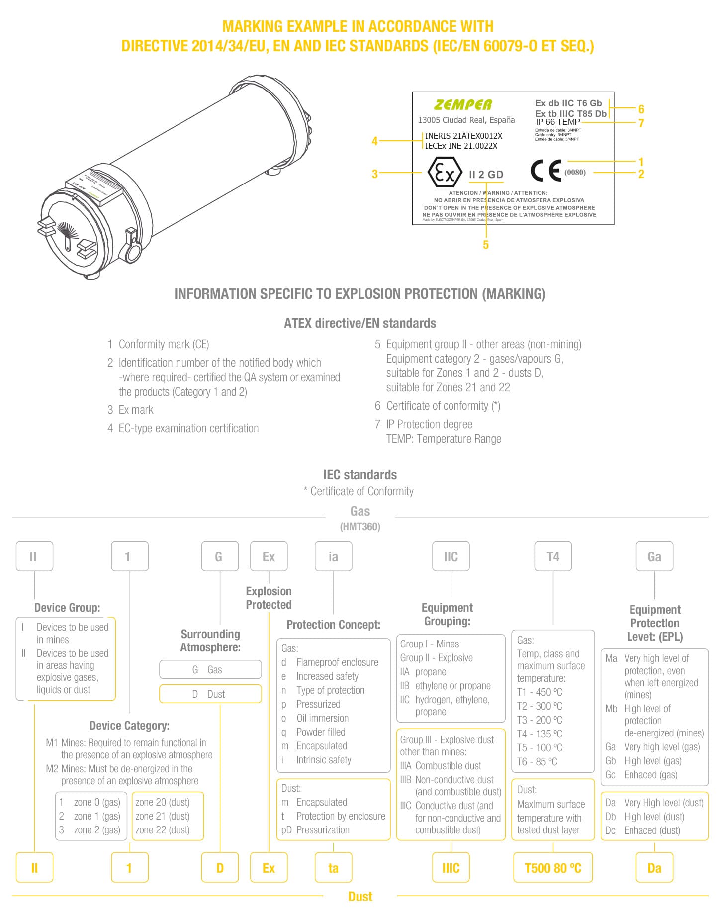
ATEX Hardware Labelling

Please see below for the Zemper example for cross reference purposes.

Awareness in hazardous area concepts for the use of electrical equipment
Many companies do not give adequate consideration to the condition of their electrical installations in relation to potentially explosive atmospheres, especially within older plants. Let’s look at the importance of maintaining focus on electrical issues during ATEX inspections.
Hazardous Area ATEX inspections: industry oversight
Whilst many companies are concerned with ensuring completion of their hazardous area ATEX inspections and demonstrating compliance with the DSEAR regulations, ATEX 137 directive and BS EN 60079-17 standard, they tend to overlook the fact that electrical testing should be equally important to ATEX inspections (BS 7671-part 6 in conjunction with BS EN 60079-14 section 4.1 General Requirements, HSE 2002, HSE: ATEX and explosive atmospheres).
There are a number of reasons why companies focus upon ATEX inspections rather than having a dual focus on both electrical and ATEX considerations. These may include a local, regional or national safety authority drive on achieving ATEX compliance; insurance requirements; organisational policy and safety processes, all of which may prioritise the requirement of ATEX inspections over electrical inspections.
In fact, it is apparent within some industries and, particularly, within smaller companies that do not possess the resources to maintain awareness of legislative compliance requirements, that there is a clear lack of awareness about compliance for electrical systems.
Organisations may conduct a hazardous area inspection and gain a satisfactory result as required by the BS EN 60079-17 standard even though the installation remains non-compliant with the required electrical inspection and verification standard BS 7671 due to outdated certification and condition reports. Moreover, in some situations, the installation and verification of electrical systems and overall safety considerations are carried out in-house by the maintenance workforce.
The problem may arise that although the workforce is highly skilled and has knowledge of ATEX hazardous area requirements, it may not have complete clarity of the most recent UK amendments to the BS 7671 wiring standard – a valuable tool which is an essential consideration of the electrical risks to new installations, plant maintenance, modifications and for the employees or contractors who install or maintain electrical equipment. The standard provides guidance towards a compliant and a safe electrical installation in line with The Health and Safety at Work Act 1974 and Electricity at Work Regulations 1998.
Furthermore, the capability of the inspectors completing the assessment should also be audited by a competent duty holder or third-party organisation proficient in both hazardous areas and electrical inspection. Certified training, experience and tacit industrial knowledge of electrical and hazardous area inspection should all be included in the competency assessment (BS EN 60079-14: 2014, Annex A & IET Guidance Note 3 – 1.2), so for example possessing a CompEx certificate will demonstrate the operative has received formal training in the basic principles of ATEX electrical installation, but this does not necessarily guarantee competency for inspection activities.
Examples of possible problem areas
Without taking adequate consideration of the risks for the electrical supplies, possible problem areas could give an overall unsatisfactory outcome. These include:
- A lack of up to date electrical installation certificate or electrical condition report.
- Undersized live conductors and voltage drop considerations – cable size and length, additional electrical equipment added to the local circuits, or additional protection by RCDs.
- Main supplying control gear and distribution equipment suitable for any increased load and the condition of control gear supplying the hazardous areas – un-serviced lighting, motors , unmaintained motor overload, spent fuses replaced by ill-fitting and un-monitored ones – overloaded switchgear and distribution equipment.
- Poor type and condition of earthing arrangement.
- Undersized main protective bonding conductors on infrastructure, structural steelwork, fabricated steelwork, process pipe-work, storage and process tanks.
- Secondary supplies – undersized UPS systems and insufficient back-up generators.
- Insufficient use of SWA (steel wire armouring) cable or braid used as a circuit protective conductor.
- Incorrect application of calculations and equations when using the appropriate technical guidance to determine conductor size.
- Lack of considerations with electrical designs when alterations are made after the initial installation – VSDs (Variable Speed Drives) paired incorrectly with specific motors.
- Lack of consideration for insufficient electrical isolation for maintenance purposes in a hazardous area – poor isolation of live conductors entering the hazardous area.
- Suitability of containment systems -.use of limited materials and appropriate – containment systems in certain classified hazardous area zones.
Electrical and Hazardous Area ATEX inspections
The list of potential problem areas is non-exhaustive and experience can dictate that every installation creates a different challenge.
With reference to BS 7671-part 6 in conjunction with BS EN 60079-14 section 4.1 General Requirements, the electrical installations in a hazardous area should also comply with the appropriate requirements for electrical installations in a non-hazardous area. However the requirements for non-hazardous areas are insufficient for installations in a hazardous area.
In fact, it could be argued that electrical and hazardous ATEX inspections are best suited when completed simultaneously, as it demonstrates that the risks have been considered for both the electrical installation and the electrical equipment within the potentially explosive atmosphere (BS 7671-part 6 & BS EN 60079-14). For the electrical installation, an inspection should be carried out followed by an electrical installation condition report (EICR), as required by BS 7671-part 6. The results of the electrical report are pertinent to the inspections required in BS 60079-17, tables 1-3.
Both the hazardous area and electrical condition reports should be utilised to ensure that the installations are maintained to a satisfactory condition for continual use and for the identification of a pass, fail or non-applicable limitation (noting that too many limitations will devalue the credibility and integrity of the information within the report) (60079-17: 2014-4.3, NICEIC EICR Report: 2013, amendment 2).
Furthermore, issues with electrical installations outside hazardous areas can have a direct effect on systems within the hazardous areas which, in turn, could result in a catastrophic occurrence.
Conclusion
Taking into account the requirements within BS 7671-part 6 in conjunction with BS EN 60079-14 section 4.1, General Requirements, it could be argued there is a general lack of awareness within some organisations of compliance to both electrical and ATEX hazardous area inspections.
There are a number of reasons which have led to this situation and although organisations may have completed their ATEX inspections accurately, the installations may still be non-compliant with the required electrical inspection and verification standard BS 7671.
Organisations may conduct a hazardous area inspection and gain a satisfactory result as to the inspections required in the BS EN 60079-17, although the installation may still be non-compliant. The proficiency of the inspectors conducting the inspections should also be assessed and audited accurately by a competent duty holder or third party. Certified training, experience and tacit industrial knowledge should all be included within such competency assessment.
BS7671 is the UK electrical installation industry standard and is a most valuable tool for the consideration of the electrical risks for new installations, plant maintenance, modifications and for the employees or contractors who install or maintain electrical equipment – the primary reason for ensuring that an electrical inspection is conducted is to ensure that the supplies into the hazardous ATEX area are adequate and safe for the application.
Unsatisfactory electrical installation scenarios vary greatly as previously described where the list is non-exhaustive and experience dictates that every installation will pose a different challenge. Condition reports must be utilised to ensure electrical systems are installed and maintained to a satisfactory condition.
Ultimately, whilst electrical installations in a hazardous area must comply with the appropriate standards for a non-hazardous area, the requirements for non-hazardous areas are technically insufficient for installations where potentially explosive atmospheres have been classified.
Electrical and hazardous areas ATEX Inspections should be completed simultaneously in order to demonstrate that the risks have been suitably assessed and provide, as far as reasonably practicable, a safe installation. Conducting electrical and hazardous area ATEX inspections as part of any maintenance strategy will minimise the risk of a catastrophic occurrence.
References
1. BSI. (2008). BS 7671:+A3 2015 Requirements for Electrical Installations. IET.
2. BSI. (2014). BS EN 60079-14: 2014 Explosive Atmospheres: Electrical installations design, selection and erection. BSI.
3. BSI. (2014). BS EN 60079-17: 2014 Explosive atmospheres. Electrical installations inspection and maintenance. BSI.
4. Copyright, C. (1998). The Electricity at Work Regulations, 1998. Retrieved February 20, 2015, from legislation.gov.uk: http://www.legislation.gov.uk/uksi/1989/635/contents/made
5. HSE. (n.d.). ATEX 137: ATEX and explosive atmospheres. Retrieved February 20, 2015, from HSE: http://www.hse.gov.uk/fireandexplosion/atex.htm
6. HSE. (2002). Dangerous Substances and Explosive Atmospheres Regulations 2002. Approved Code of Practice and guidance. HSE (Health and Safety Executive.
7. HSE. (1974). Health and Safety at Work etc Act 1974. Retrieved February 20, 2015, from HSE: http://www.hse.gov.uk/legislation/hswa.htm
8. NICEIC. (2013). Amendment 2: The Electrical Installation Condition Report (EICR). NICEIC.

